How to Install a Vertical Busbar System?
EAE Electric makes energy distribution safer and more sustainable with its modular Busbar Systems and Support System solutions that eliminate cable clutter in high-rise buildings. We examine the vertical installation of the E-Line KX Busbar step by step.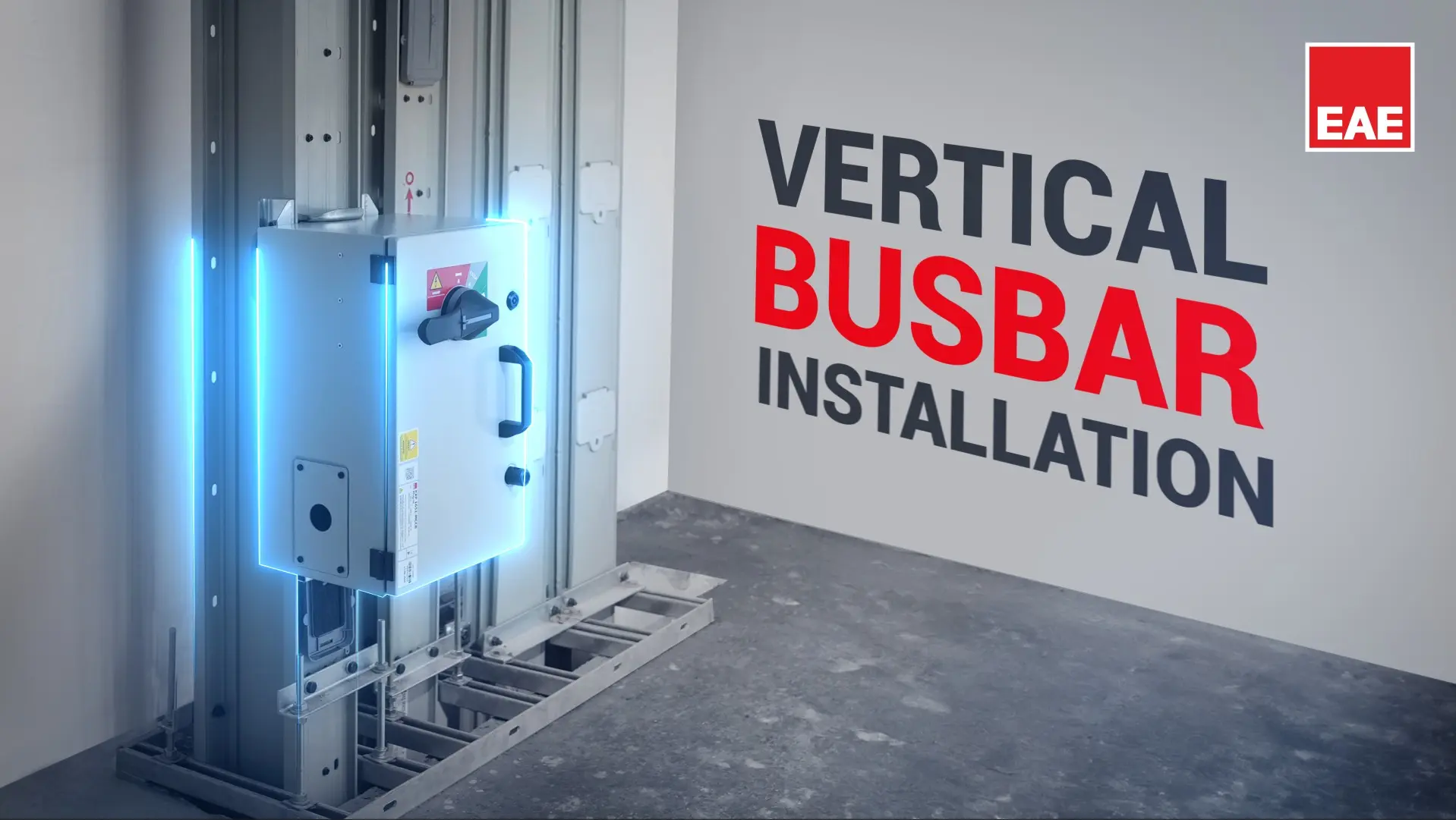
EAE Electric makes energy distribution safer and more sustainable with its modular Busbar Systems and Support System solutions that eliminate cable clutter in high-rise buildings. From plazas to hospitals, from shopping malls to data centers, vertical busbar lines form the backbone of distribution in all structures with high energy demand. How is a Vertical Busbar System installed, and what are the key points to consider? We examine the vertical installation of the E-Line KX Busbar step by step.
Why Is It Critical for High-Rise Buildings?
In high-rise buildings, the biggest challenge of energy distribution is safely and efficiently carrying multi-floor loads within limited shaft space. Traditional cable bundles become insufficient beyond certain current capacities in terms of space occupancy, heat buildup, and fire load. This is exactly where Vertical Busbar Systems come into play.
Thanks to the modular structure of the Busbar System, it is possible to install a tap-off box on each floor to supply power directly. Instead of running separate cables to each floor, distribution can be achieved to all floor panels via a single vertical line. This results in fewer connection points, lower risk of failure, reduced voltage drop, and significant space savings.
The aluminum housing and high IP protection classes support safe and long-lasting operation of the busbar lines. When building expansion or capacity increase is required, specific sections of the line can be dismantled and replaced, providing great flexibility for future modifications.
Support Systems in Horizontal and Vertical Installation
The proper operation of busbar lines is directly related to the correct planning of mechanical supports. The distance between support points is recommended to be minimum 1.5 meters and maximum 2 meters. This spacing limits mechanical oscillation and keeps the load applied to joint points within a safe level. Support positions should be planned so as not to obstruct joint covers and tap-off outlets.
For horizontal applications, standard clamps and threaded rod hangers are sufficient. If the Busbar system passes through a building expansion joint, an appropriate expansion joint module must be selected within the scope of the project; these modules compensate for dimensional changes caused by temperature variations and building movements, thereby protecting the system from mechanical stresses.
In vertical applications, the situation is more critical. The busbar system must be fixed at every floor transition; the DDT modules used on the concrete slab should be positioned at 20 cm intervals. In multi-path high-rise building applications, due to differences in floor heights, slab thicknesses, and product tolerances, the alignment of tap-off windows and joint points may not be exactly the same on every floor. Therefore, alignments must be re-measured and continued at each floor. For this reason, proper alignment of tap-off boxes and ensuring that the joint point does not coincide with the floor transition are of critical importance.
In regions with a high earthquake risk, seismic support systems must be used. Instead of standard hangers, rigid seismic hangers designed to withstand vibration and ground movement should be used to maintain the integrity of the busbar system. In geographies with high seismic risk, such as Türkiye, it is essential that this requirement is not overlooked during the design stage.
Ensuring fire compartmentation at shaft penetrations is critical. At every point where the busbar system passes from one fire compartment to another, the opening must be sealed with firestop materials (such as mortar, fire pillows, panels, etc.), with a fire resistance rating at least equal to that of the respective compartment. Highly fluid firestop mortars should be avoided; leakage must be prevented from reaching the joint points.
Installation Steps
The vertical KX busbar installation follows a specific sequence on site. In the video below, you can view the complete installation process:
- • Preparation: Safety measures are reviewed, and pre-checks are carried out for vertical installation.
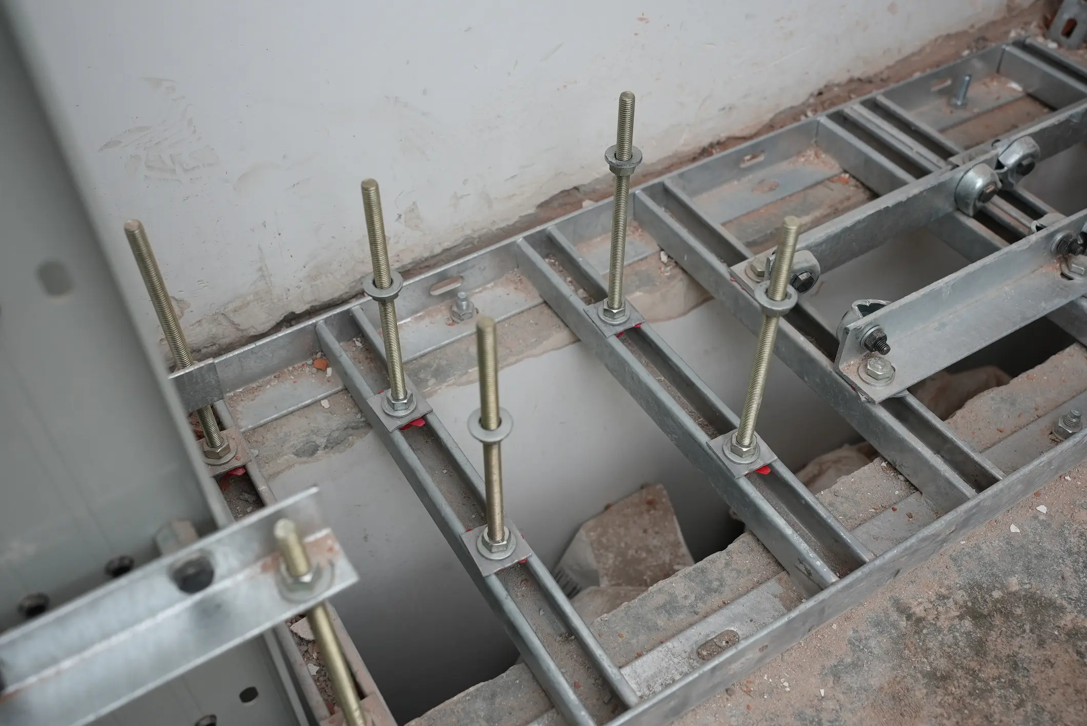
- • Fixing elements: Spring hanger brackets are fixed to the floor and adjusted.
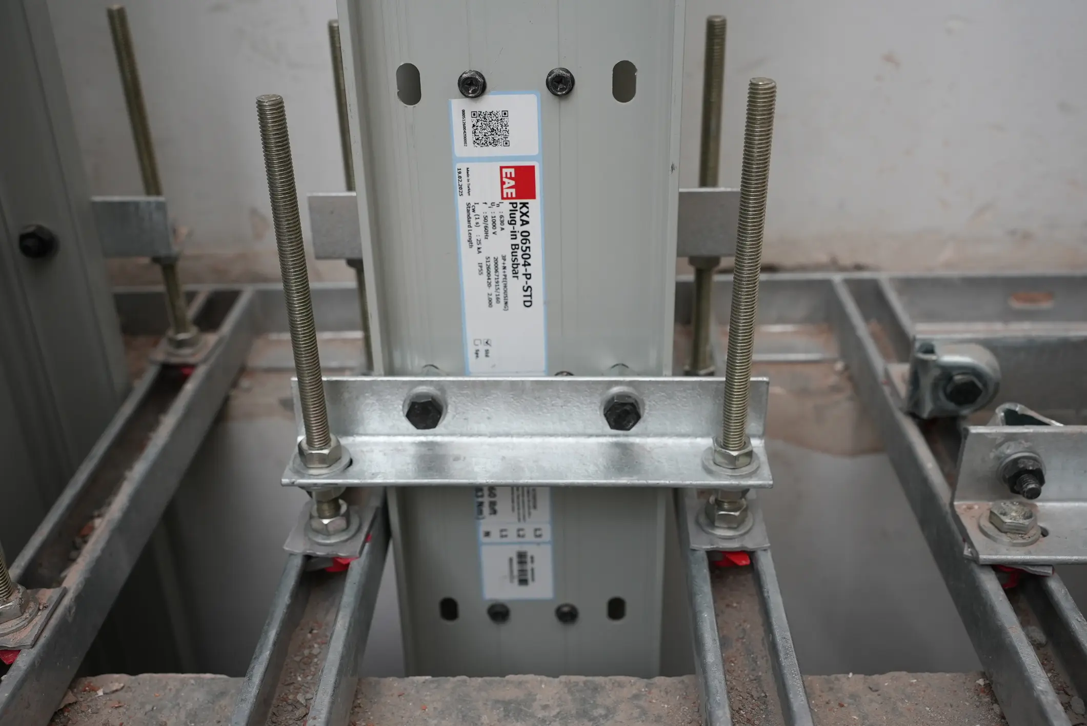
- • Module handling: Vertical busbar modules are positioned and transferred between floors.
- • Joint assembly: The joint block is placed in position and tightened using a torque wrench.
- • Alignment and fixing: Modules are aligned, and final tightening of the hangers is completed.
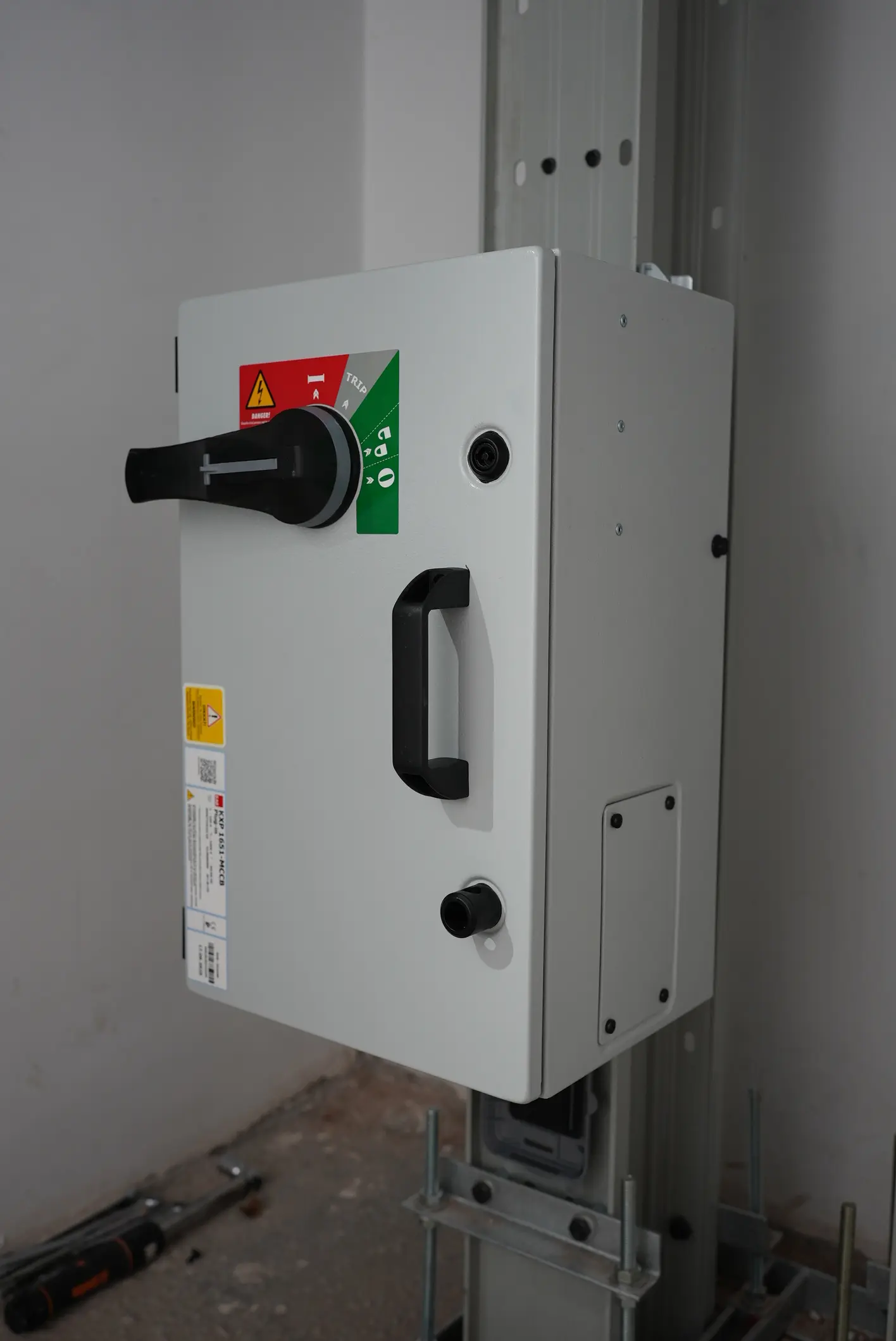
- • Final checks: Protective covers are installed and the installation is completed.
Before energization, it must be verified that all tap-off boxes are in the "OFF" position, the insulation resistance test (minimum 1000 V AC) has been completed, and the phase sequence is correct. The system shall be energized under the supervision of authorized personnel, starting from the source end and proceeding sequentially towards the load side.
Frequently Asked Questions
In the E-Line KX vertical busbar system, the joint center bolt is tightened using a calibrated torque wrench set to 83 Nm (60 lbft). In single-bolt constructions, Belleville (disc) washers on both ends of the bolt maintain constant contact pressure under all thermal conditions while also preventing loosening of the bolt.
For joints with two or more bolts, tightening is carried out in two stages: first a pre-tightening at 20 Nm (in the sequence 1→2→3→4 and 5→6→7→8), followed by final tightening at 83 Nm using the same sequence. After tightening, the lock nut component must be tightened to 20 Nm, and the cover gasket must be properly lubricated.
In the E-Line KX system, the maximum current rating of the tap-off box varies depending on the type. Bolt-on tap-off boxes allow current draw up to 1000 A, while plug-in tap-off boxes allow current draw up to 630 A.
| Busbar Tap-Off Box Type | Current Ratings |
|---|---|
| KXB (Bolt-on) | 160 A, 250 A, 400 A, 630 A, 800 A, 1000 A |
| KXP (Plug-in) | 160 A, 250 A, 400 A, 630 A |
The current drawn from a tap-off box must never exceed the busbar's rated current. When selecting a unit, the total load current to be supplied, the usage profile, and the protection device (circuit breaker) rating must all be evaluated together. In addition, bolt-on units must not be installed on plug-in windows, and plug-in units must not be installed on bolt-on points; 4-wire units must not be connected to a 5-wire busbar (or vice versa).
A busbar expansion element compensates for dimensional changes caused by temperature variations and protects the system against mechanical stress. If the busbar line passes through a building expansion joint, an appropriate expansion module must be used. DDT modules used on concrete slabs should be positioned at 20 cm intervals. In cases where the line is used in special lengths or configurations, the number and position of expansion modules are determined on a project-specific basis.
For indoor vertical shaft applications, the E-Line KX busbar system is standardly manufactured with an IP55 protection class, providing protection against dust and water jets from any direction. For applications requiring higher protection levels, IP65 and IP67 options are also available. Shaft openings must be covered at the top, and to prevent liquid ingress into the shaft, a minimum 100 mm high upstand should be constructed around floor openings where vertical busbar runs pass through.
Since every building has a different structure, a dedicated project design is carried out for E-Line KX vertical applications. Due to differences in floor heights, slab thicknesses, and product tolerances, tap-off window or joint point alignments on upper floors may not match those on lower floors. Therefore, to ensure proper alignment of tap-off boxes and to prevent joint points from coinciding with floor transitions, measurements must be taken on each floor and installation must continue accordingly. In addition to standard 3-meter lengths, custom-sized modules can also be manufactured, ensuring full compatibility with the building's architecture.